Robot Segmentation
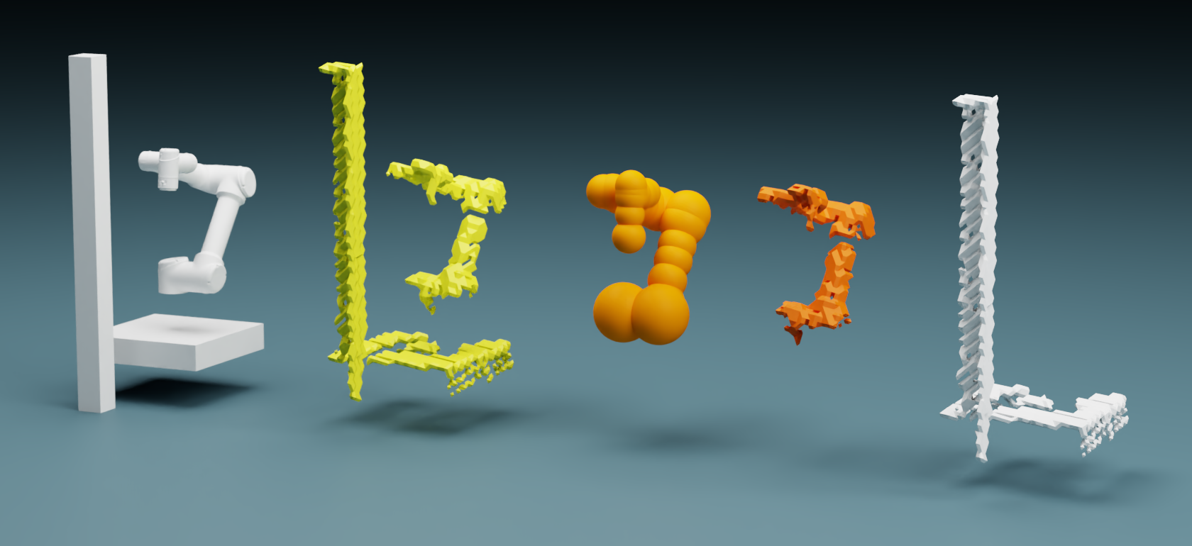
Steps in filtering a robot using cuRobo’s robot segmentation. The scene shown in left is seen by a depth camera. The depth image is converted to a pointcloud and transformed to the robot base frame as shown in yellow (second from left). The current joint configuration is used in cuRobo’s kinematics to obtain the position of robot’s spheres as seen by the orange spheres (third from left). Points within these spheres are subtracted out (fourth image from left) and the final pointcloud is obtained with no robot visible (rightmost image). This pointcloud is converted back to a depth image and returned, along with a mask label.
The geometry of a robot in a depth image can be filtered/segmented using cuRobo’s kinematics and
geometry distance queries. This is available through
curobo.wrap.model.robot_segmenter.RobotSegmenter which can be initialized with a robot
configuration file. Once initialzed, you can pass in curobo.types.camera.CameraObservation
with depth_image, intrinsics, and pose (with pose of the camera w.r.t. robot’s base frame), and
the robot’s joint configuration as a curobo.types.state.JointState. Internally, the
function first generates a pointcloud from the depth image using the intrinsics and then transforms
the pointcloud to the robot’s base frame. Then position of the spheres representing the robot geometry
are computed using cuRobo’s kinematics. Finally distance between the pointcloud and spheres are
computed and any point within a distance threshold are treated as robot points and filtered.
Check examples/robot_image_segmentation_example.py for reference. cuRobo’s implementation wraps
the operations in a CUDA graph to reduce python overheads, achieving 3000hz on a 4090 GPU for
480x480 images.
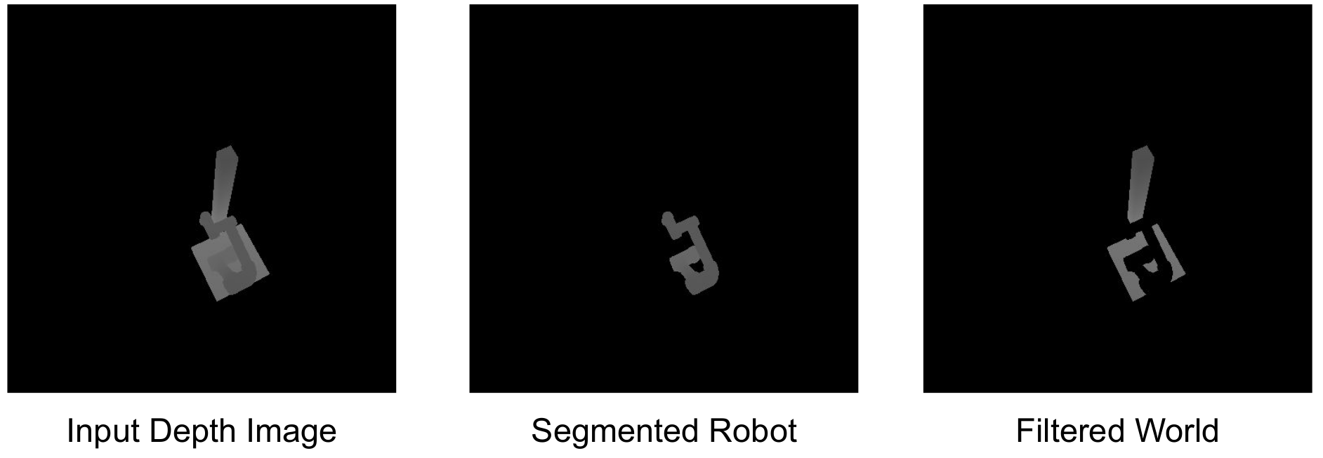
The depth input depth image is shown in the left, followed by the segmented robot in middle and world without robot in right.